After Directing Imaging (DI) of copper layers, Direct Imaging of Soldermask redefines the boundaries for the soldering of SMD components.
Direct Imaging is the biggest technological advancement for the manufacturing of PCB’s in the last decade.
Since we introduced the Ledia Direct Imaging system (DI) for Soldermask exposure at Eurocircuits, we have been working hard to find its optimum registration capabilities.
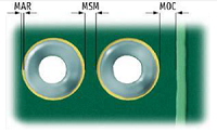
As a result we can now offer improved registration capabilities for Soldermask and we are now able to reduce the minimum required clearances for DI compatible Soldermask as below:
MAR to 0.030mm…from 0.060mm
MSM to 0.070mm…from 0.100mm
MOC to 0.060mm…from 0.100mm |
 |
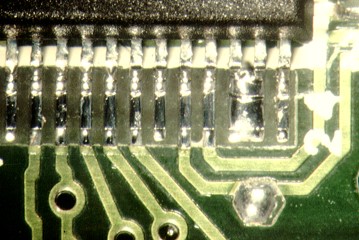
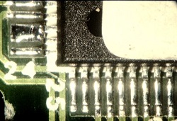
Due to the improved registration it is possible to have Soldermask between the pads of fine pitch components and this helps to protect against solder bridging as below.
|
| DI Soldermask |
Conventional Soldermask |
 |
 |
Smaller Soldermask openings give designers another big advantage, as it allows for tracks to be routed closer to pads.
From a manufacturing point of view, using DI for Soldermask has many advantages. For example, we can switch from one job to another in a matter of minutes as there is no need for films which is a timely process as used on conventional exposure systems.
DI Soldermask demands a premium price from our supplier, however, Eurocircuits believe the benefits out-way this additional cost and does not charge extra for the use of DI Soldermask.
We want our customers to benefit from using DI Soldermask and we see it as a win-win for everyone.
Available colours for DI exposure, at present, are Green, Red, Black and Blue.
For more information please see our PCB Design Guidelines – Soldermask Section.

|