Edge Connectors
Introduction
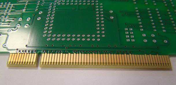
Edge connectors are generally used for connecting one PCB to another, the edge connector is plugged in to a socket on another PCB thus making the connection.
Examples of this can be seen on a computer motherboard where you plug a graphics card with a gold edge connector into the socket on the mother board.
The surface finish of edge connectors is usually with what is known as Hard Gold on top of nickel, this allows for the repeated plugging and unplugging of the connector.
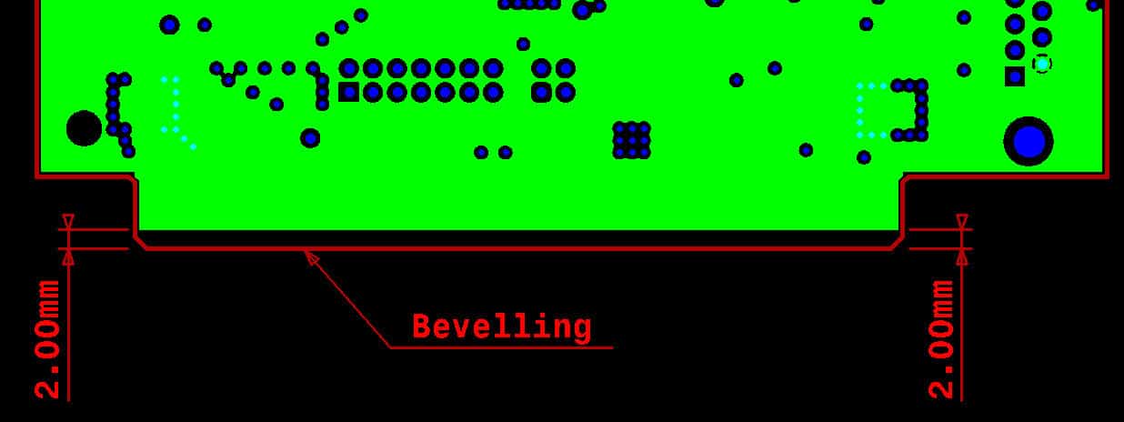
To help guide the edge connector into the socket they need to have a bevelled leading edge.
Specification
Description |
Specification |
| Maximum Pad Length | 40mm |
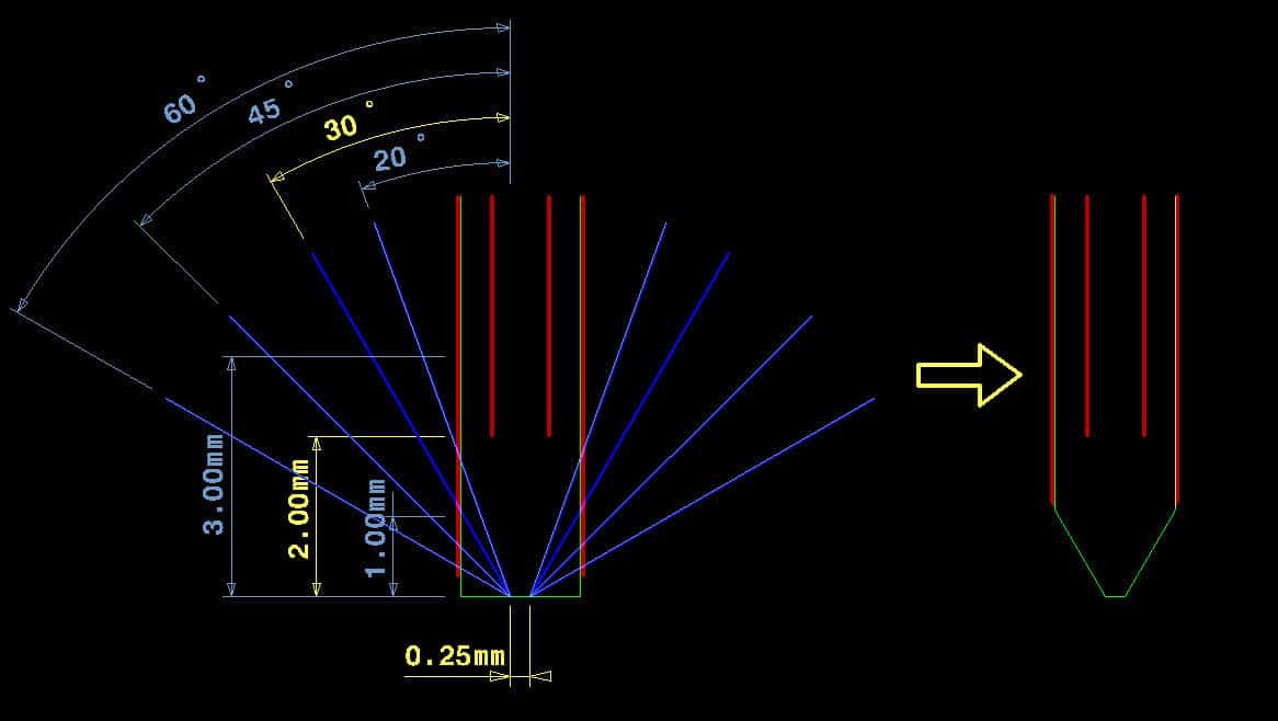
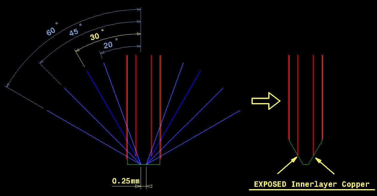
| Inner layer Copper to Board Edge Clearance | 20o – 3.00mm 30o – 2.00mm 45o – 1.00mm 60o – 1.00mm |
| Minimum Finger Width | See our Classification Table for the minimum Outer Layer Track width (OTW) and Track to Track (TT) distance |
| PTH to Edge Connect Clearance (edge to edge) | 2.00mm |
| SMD Pad to Edge Connect Clearance (edge to edge) | 2.00mm |
| Copper Feature to Edge Connect Clearance (edge to edge) | 2.00mm |
| Minimum PCB Thickness | 1.00mm |
| Maximum PCB Thickness | 3.20mm |
| Minimum Remaining Material Thickness – All Angles | 0.25mm |
| PCB Dimension Perpendicular to Edge Connector for Standard Bevelling | Minimum – 40mm Maximum – 400mm |
| Bevel Angle | Standard – 30o Special – 20o, 30o, 45o, 60o |
| Distance between Edge Connectors on Opposite side of the PCB | 150mm |
| Customer Panel Layout | See Panel Guidelines |
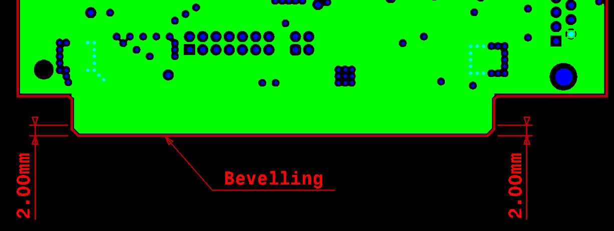
Bevelling
Also known as chamfered edges.
There are two types of bevelling available for edge connectors as below:
Standard
- Standard bevelling is machined on the bevelling machine.
- Only 30 degrees angle possible.
- Only possible for edge connectors on an accessible outside edge of a single PCB.
- The PCB dimension perpendicular to the bevelled edge must be minimum 40mm and maximum 400mm.
Special
- Special bevelling machined on the rout machine.
- Available at angles of 20, 30, 45 or 60 degrees.
- Bevelling is Special it cannot be done on the bevelling machine:
- Bevelling “inside” of an accessible outside edge of a PCB.
- Bevelling “inside” of the PCB contour.
- PCB dimension perpendicular to the bevelled edge less than 40mm or more than 400mm.
- Bevelling on PCBs in a customer panel.
- Other than 30 degrees angle.
Copper Clearances
Outer Layer Clearances
Do not place any plated holes (PTH), SMD or other pads closer than 2.00mm (Dimension D) to the inner edge of the edge connector fingers.
Copper Clearance on Inner Layers
The minimum copper free area on inner layers is to prevent exposed inner layer copper at the bevelled edges.

