User Guides
Our User Guides provide step-by-step instructions on how to use our free online smart tools and other available software.
It is very important to get exact information about the orientation of symmetrical components, This is why it is recommended to indicate the first pin of the component on the legend layer. Accepted marking could be a dot, a line or a ‘1’ symbol in accordance with the datasheet of the component.
If there is no pin 1 marking in the component datasheet, then please use text that helps identifying the orientation. The symbol of the component should define the orientation. A good example can be seen here:
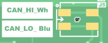 Legend on the PCB marks pin 1 |
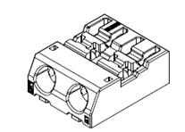 Shape of the component |
As with SMD components it is also important to know the orientation of polarised through hole components and connectors. The Legend layer should identify pin 1. If there is no information for pin 1 in the datasheet of the component then the outline of the component could be used to give appropriate information as shown below.
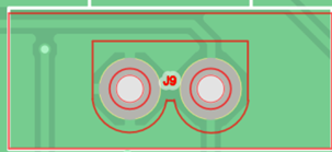 Use legend to indicate the rotation. |
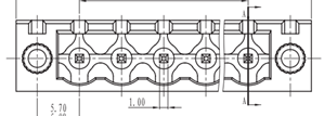 Shape of the component |