The Panel Editor is part of the PCB Visualizer and allows you to view, create and modify panel layouts for your PCB’s whether it is a step & repeat of a single PCB layout or the nesting of multiple PCB layouts.
There are tools for adding fiducials, tooling holes, text, spacers, rotating the PCB, frame and border elements.
Using the Panel Editor allows you to check the panel on-screen and order with confidence.
Please see our Panel Guidelines for more information about creating panels.
See separate sections for each topic. If you have any questions, use our online chat line to talk to one of our engineers.
1. USE PANEL EDITOR TO GET A FAST PRICE WITHOUT UPLOADING DATA?
Most Panel Editor options can be used before you upload your data. For this, PCB Visualizer uses a dummy PCBs of the size you enter.
There are three panel options.
eC Panel by Eurocircuits
Customer Panel by Eurocircuits
Customer Panel by Customer
For more information on these panel formats please see our Panel Guideline.
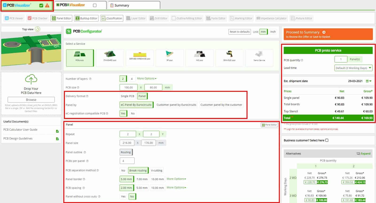
To select PCB’s delivered in a panel format select panel next to Delivery format. If you selecting eC-panel by Eurocircuits or Custom Panel by Eurocircuits this will automatically open the Panel menu.
Selecting the Delivery format as panel opens the Panel section – enter the values for the panel and a price will automatically displayed.
eC-panel by Eurocircuits
Specify the repeats you want in X and Y. Select the panel border, and the PCB spacing from the pull-down boxes.
All eC-panels are compatible with our eC-registration system and have all the necessary tooling holes to use with our eC-stencil-mate or eC-stencil-fix (eC-Stencil required).
As they also have our standard pattern tooling holes and fiducials and are 100% suitable for use with other registration systems.
Click Panel editor to see the panel with the dummy PCB’s.
Customer panel by Eurocircuits
Click the Panel editor wizard and proceed as below to specify the step and repeat, border and separation distance required. Ignore the red warning message about the 0,0 panel size – this will be changed by the Panel editor. PCB Visualizer will display the default board size, so for an accurate price enter the correct circuit size, make any other size changes required and click Apply.
TIP – Don’t put in the border elements at this stage as they will be lost when you upload the real board data.
Customer panel by customer
Use this panel option if you have already prepared data files with the complete panelisation for a special layout or for a multi-panel (panel with several different designs).
Your layout should meet our panelisation requirements (see our Panel Guideline) for panel border and distance between the circuits.
This option will not open Panel Editor as the files will be display as you have created them in PCB Visualizer.
TIP – All delivery panels require a border to hold them together during transport and handling. If you have not included a border or want to put additional features into the border, select Custom panel by Eurocircuits and specify a 1-up panel using the Panel Editor.
2. VIEW OR MODIFY EC-PANEL BY EUROCIRCUITS
Step 1. Load the job into PCB Visualizer
Sign-In to your Eurocircuits customer account and upload your data, click “Add to basket” and your data will be analysed. Alternatively, select the job from your customer account shopping basket.
Step 2. View eC-panel by Eurocircuits.
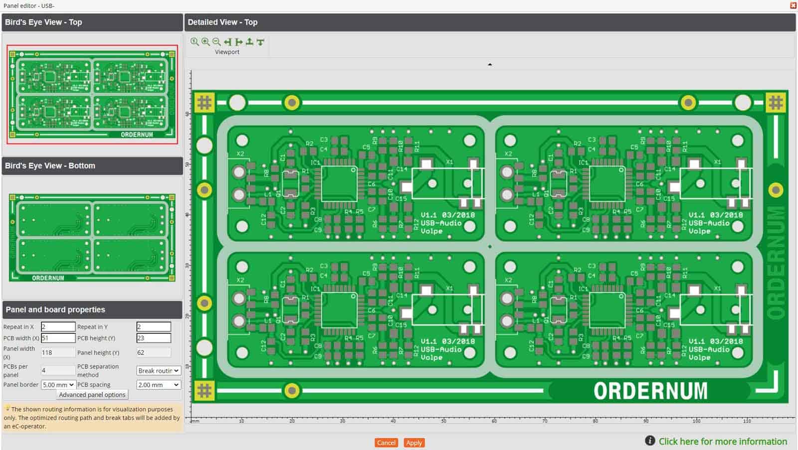
If you have already specified the step and repeat, border size, PCB separation method and distance, click the Panel editor to see the panelised circuit.
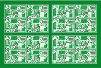
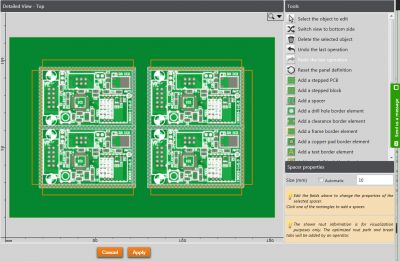
The Panel Editor
NOTE – The router path is shown as a hatched area. Our engineers will place rout tabs in this area to ensure a stable panel.
TIP – If there are areas in which you do not want rout tabs to appear due to sensitive components etc., specify them in a mechanical drawing.
You can now change:
Repeat in X and/or Y
PCB separation method
Panel border
PCB spacing
For any other changes, click “Advanced panel options”.
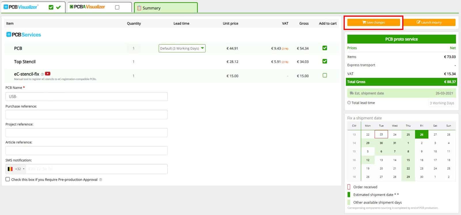
Click “Apply” at the bottom of the screen and the price in PCB Configurator will open and the price will be automatically updated.
Click the on the “Summary” tab at the top of the page, this will open the summary page and click on “Save changes” to save the changes.
Click on the “Summary” tab at the top and the the “Save changes” button to save the changes in the Hopping basket.
Movie – Create and view an eC-panel with panel editor
3. LAY OUT A CUSTOM PANEL BY EUROCIRCUITS.
Step 1. Load the job into PCB Visualizer as Section 2 step 1 above
Click the “Panel Editor” button.
Ignore the red warning about the 0,0 panel size – the Panel Editor will complete the correct size.
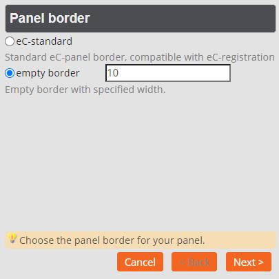
Step 2. Select the panel border and enter your preferred value
Select your panel border and enter your preferred value
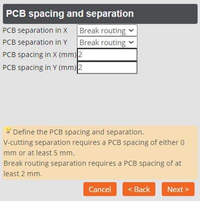
Step 3. Enter the PCB spacing and separation method
Enter the PCB Spacing and Separation setting
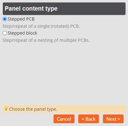
Step 4. Choose the panel content type
Choose the panel content type.
Select:
Stepped PCB if you want to build your PCB out of single circuits.
Stepped block if you want to build your panel out of a custom block of two or more interlocked or “nested” circuits, typically L- or T-shaped. For this option, see below.
Step 4. Select “Stepped PCB”. And click “Next >” button.
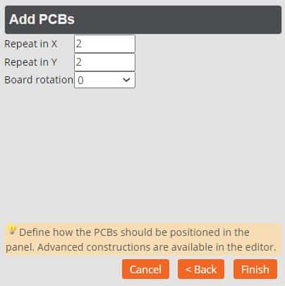
Step 5. Set up the basic step and repeat
Set-up the number of PCB’s in X 7 Y and rotation of required.
You can also add a rotation to the PCB’s if required.
Additional options are available in the editor.
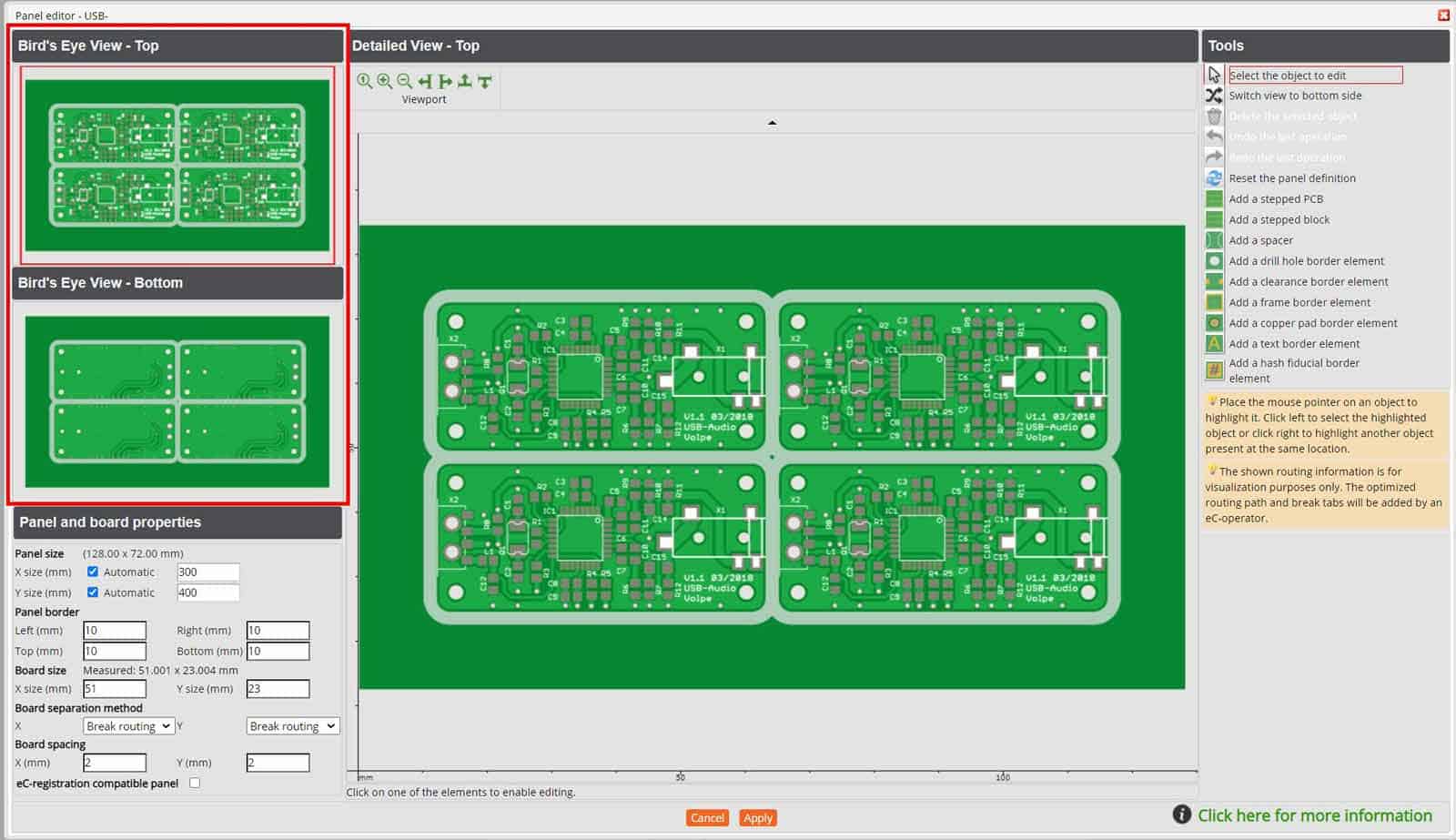
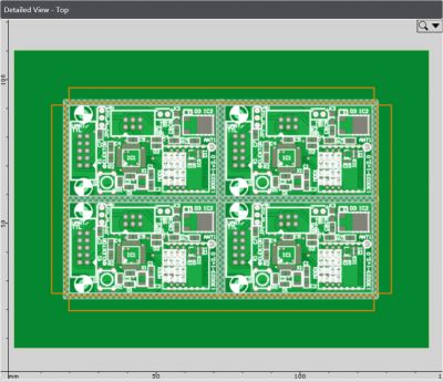
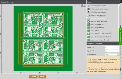
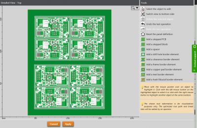
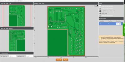
Step 6. The Panel Editor show birds-eye view
You will also see the Panel and PCB properties menu and the panel tools menu.
Birds-eye view of the panel where you can switch between the top and bottom view.
Swap top and bottom views by clicking on the bird’s eye menu, or using the tool menu icon.
Pan and zoom with your mouse or use the tool in the View port menu.
TIPS
For hints and tips on designing stable panels including panelising round circuits and handling overhanging and heavy components please see our Panel Guideline.
If you are using an external assembly company and they supply a detailed dimensioned drawing of their requirements, you may find it easier to use the Launch inquiry route to get a price. Upload your single circuit data, the drawing and your step and repeat instructions (as a README file) and our engineers will lay out the panel and give you a price. This may take up to 1 working day.
4. CHANGE PANEL AND BOARD PROPERTIES
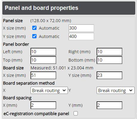
Change the panel and PCB properties in this menu.
Use this menu to change:
Panel size
Panel border
Board separation method
Board separation distance
Alternatively, add eC-registration compatible holes if you want to use a solder-paste stencil with our eC-stencil-mate or eC-stencil-fix.
TIP – If the board size is incorrect, PCB Visualizer will show a dummy panel. Correct the size in the menu (“Board size”).
5. CHANGE THE STEP AND REPEAT OF THE JOB
Click within the existing stepped circuits to select the block. This opens the “Stepped PCB properties” menu. You can now change the repeat and the rotation of the PCB.
Change the step & repeat values
6. TO “FILL” A PANEL
Deselect the Automatic X and Automatic Y boxes in the “Panel and board properties” menu.
Select the panel size you require (e.g. the Eurocircuits recommended maximum panel 350 X 250 mm, or your assembly company’s maximum size e.g. 300 x 200 mm).
Use the “Step/repeat block properties” menu to change the step and repeat and rotation to find the best fit.
Select the Automatic boxes to get the final panel size.
7. DEFINE SPECIAL PANEL SETTINGS
Stepped PCB.
Stepped Block.
Block (Custom block of nested PCBs: L-shapes, T-shapes, etc…).
These allow you to customise your panel layout.
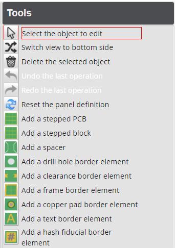
Tools
Panel Editor Tool Panel
TIPS
To deselect a tool, double-click the Select button or pick the next tool.
To select a border element that is below another border element, you need to click with the right mouse button to first highlight it (orange border), then you can click with the left mouse button to select it.
Use “Reset the panel definition” to:
Restart the Panel wizard – select “Create new panel definition”.
Clear everything and go back to the PCB Configurator menu – select “Clear panel definition”.
Create or reset panel definition.
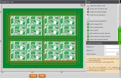
7.1. Add stepped PCB pattern
Use this function to step and repeat PCB blocks or to add rotated PCB’s.
Click the tool “Add stepped PCB’s”.
Select the orange location box where you want to repeat the same circuit pattern.
Stepped PCB Pattern
This opens the “Stepped PCB properties” menu. Enter the repeat values you require and click the location boxes as required.
Stepped PCB Properties Menu
By default PCB Visualizer will retain the last repeat values used. If these are incorrect, simply change them and the screen image will correct automatically.
Add spacers as required to control the distance between the blocks. Click “Select the object to edit” to clear the location boxes and show the true distances.
Add spacers as required to control the distance between the blocks.
The spacers change the distance between the blocks of circuits, not the individual circuits. Change the distance between circuits in the “Panel and board properties” menu.
7.2. Rotated blocks
There are two ways to panelise with rotated and non-rotated circuits depending on your requirements. To build a panel with rotated circuit patterns, follow the procedures here. To put rotated and non-rotated in a set, see below.
Click the tool “Add stepped PCBs”.
Select the orange location box where you want to add the rotated pattern.
Enter the required repeat and rotation values.
To rotate a block enter the rotation required
Add a spacer to control the exact distance between the blocks.
Spacers to control the distance between the blocks.
7.3. Panelise with stepped blocks (“nested” PCBs)
Use this function to interlock (“nest”) L-shaped or T-shaped PCBs.
Open the Panel editor.
Select the border required.
Set your preferred PCB spacing and separation.
Set the Panel content type to “Stepped Blocks”.
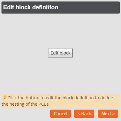
Click “Next>” to open the “Edit block definition” box. Click “Edit block”.
Select Edit Block to nest PCB’s
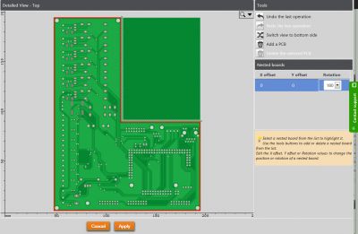
This opens the editing screen.
Editor for Nesting PCB’s
The offset will normally remain at X = 0, Y = 0 for the first circuit. For the demo job, change the rotation to 180°.
Block Editor Rotated PCB
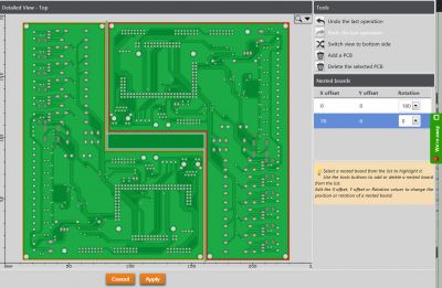
To add a second circuit, click “Add a PCB”. To avoid a second circuit being placed directly over the first circuit, it is given a notional offset, roughly 20% of its X & Y dimensions.
Block Editor with second PCB added without offsets
Add the desired offsets for the finished set. Click “Apply” to return to the wizard.
Offset applied to second PCB
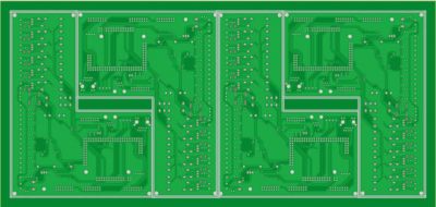
Click “Next>” to move to the “Define step values menu”. Enter your preferred repeat and click “Finish”.
Enter step & repeat values.
Panelised nested PCB’s
7.4. Add a spacer
Use this function to increase the width of a single border or the space between blocks of circuits.
Select “Add a spacer” tool.
Click on the orange locator box where you want to insert the space.
Enter your chosen spacer value.
Add spacers to set the exact space between blocks.
Click on “Select the object to edit” or “Apply” to show the new image.
TIPS – Select the “Automatic” box if you have a fixed panel size which the circuits do not fill exactly and you want to maintain for example, the relationship between the circuits and the panel edge. The automatic spacer will push the circuits into the required position.
8. DEFINE CUSTOMER SPECIFIC BORDER ELEMENTS
To see how these different options work together, see the illustration of an eC-panel above or the finished panel at the end of this section.
All border elements are dimensioned from 8 reference points. These are placed in the middle of the laminate border in the 4 corners and on the centre line of the panel. For each tool click the tool, select the (first) reference point, and the tool menu will open.
Border elements (except drill holes) can be placed on copper, soldermask or legend layers, and on top, bottom or both sides.
Adding reference points to the panel
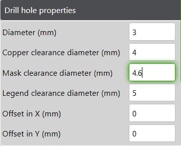
8.1 Add a drill hole border element.
Select the “Drill hole border element” tool and the reference point.
Enter the drill hole diameter plus the copper, soldermask and legend clearances and any offset required.
Add drilled hole value and clearances
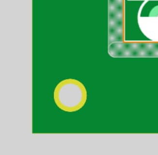
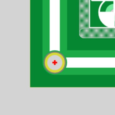
Click to insert the hole. Select the next reference point – the values entered will carry over.
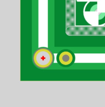
Example of a tooling hole (white) and and clearance (yellow).
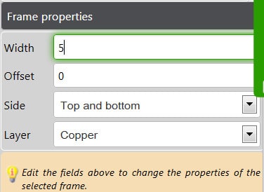
8.2 Add a frame border element
Enter the required values for the frame properties.
Specify the width, the side and the layer required (copper, soldermask and/or legend). Unless an offset is specified this will appear in the centre of each border.
Copper and Legend Frame Clearance
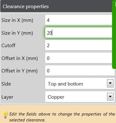
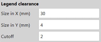
8.3. Add a clearance border element
Tooling holes, fiducials and text come with automatic clearances to your chosen values. Use the clearance function if you need to clear copper, soldermask or legend for any reason.
Input the required values for the clearance.
The cut-off allows the corner to be rounded.
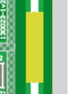
Clearance feature (yellow).
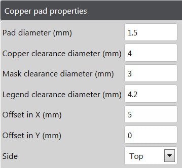
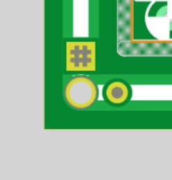
8.4. Add copper pad
Add the values for the copper pad.
For example as a fiducial. You can specify the pad size, the clearances from copper, soldermask and legend, and the offset from each reference point.
Copper pad (grey) with clearance (yellow).
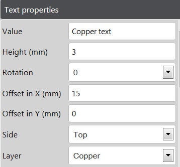
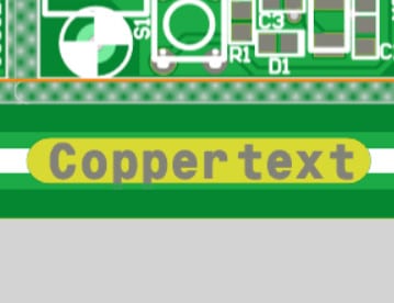
8.5. Add text border element
Input the values for the text.
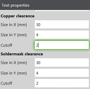
Add the cut-off value for the text.
Input the required clearance for the text.
Enter the text, dimensions, layer (copper, soldermask or legend), and the clearances required. The cut-off value gives a curved clearance.
The soldermask and legend clearances will default to the copper values but they can be changed if you prefer.
Copper text with clearance (yellow).
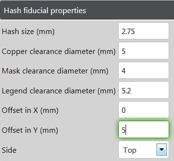
8.6. Add hash fiducials
Input the values for the Hash fiducials.
You can set copper, soldermask and legend clearances for hash fiducials.
Hash fiducial with clearance (yellow).
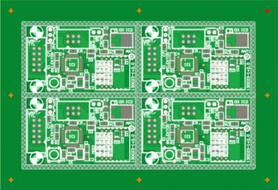
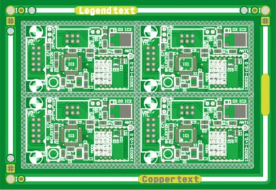
8.7. Finished panel
Including eC-compatible tooling holes.
finished panel with fiducials and text.
MOVIE: Use the panel editor to create your own custom panel
9. SPECIFY PANELS WITH SEVERAL DIFFERENT CIRCUITS (“MULTI-PANELS”)
PCB Visualizer has been developed as a Gerber file analyser to run Design Rule (DRC) and increasingly Design for Manufacturability (DFM) checks on single circuits.
There is at present no functionality to allow you to import and place interactively separate circuits into one delivery panel.
If you want to put several different circuits on one delivery panel, you have three options:
Prepare a single Gerber file for each layer including the circuits you require in the positions where you want them in the panel. Make sure that you provide a suitable border and distance between circuits.
More …
TIPS
You can use PCB Visualizer to analyse the panel as though it is a single circuit. If you need to add a border or border features, load the job as a 1 x 1 Customer panel by Eurocircuits.
To ensure optimum manufacturability we have rules for the maximum size and copper balance for panels with multiple different circuits.
Use the Launch inquiry route. Upload a single .zip file including separate .zip files for each circuits and an exact drawing how you want them panelised. Our engineers will check the data files and build the panel for you. We will send you a quotation and you will be able to see the finished panel in PCB Visualizer.
Place your order and upload a single .zip file including separate .zip files for each circuits and an exact drawing how you want them panelised. Skip PCB Visualizer. If you want to check the panel before it goes into production click the box “Request pre-production approval” in the Running menu.
10. PRE-PRODUCTION APPROVAL
Not sure about the panel you have created and need reassurance before your panel goes into production?
Our Technical guidelines offer information and best practices on various aspects of PCB manufacturing and assembly, helping you understand the processes and requirements to ensure your PCB design is suitable for manufacturing.
To simplify communication Eurocircuits uses abbreviations for many of these technical terms. Most of the technical terms and abbreviations are international standards in the Printed Circuit Board manufacturing industry. However to make it clear to everyone involved, we here present a list of technical terms and abbreviations along with their explanation.