eC-reflow-mate versus throughput reflow and controlled pizza ovens
The differences between reflow ovens explained
The cheapest solution by far for reflow soldering boards is to use a cheap pizza oven and a temperature controller. Controlling the solder curve is rather easy as the oven heats fast and cools fast due to bad insulation.
But what are possible problems?
- These ovens have a small soldering area in the middle of the oven where the Delta T is small enough to solder the whole board. So the board size that can be soldered is rather small.
- These ovens get very hot from the outside specially while using it for soldering multiple boards one after the other. This and many other points make these ovens unsafe and not fit for TüV certification.
- Controlled and fast cooling without moving the board during dwell is also not process proof
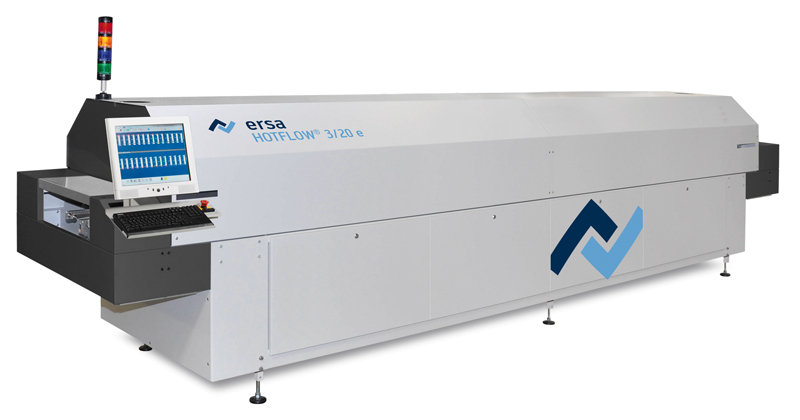
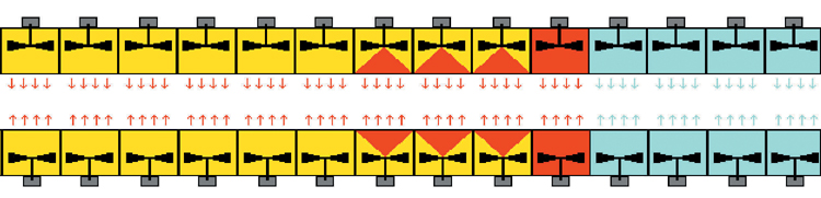
The best possible solution for reflow soldering are the professional reflow through put ovens like we have them in our assembly plant in Eger Hungary.
These ovens, with power up to 19KW, have different heat and cooling zones which are closely kept to a certain temperature. These are fixed to a specific value. Very rarely do we use another profile, for example for IMS boards. 4 to 5 profiles are used.
The variable in the whole process is the speed of the conveyor belt. And even that is rarely adapted.
It is finding a solution that works for most of the products. On the product itself there are different components with different specs but they need to pass through the oven at the same time as they sit on the same board. So also here, it is the goal to find a middle way.
In a through put reflow oven the board moves from one zone to the next, not affecting the zones itself but undergoing the effect of them on the board as the board passes through. This results in the best possible controllable process and thus soldering curve.
In the reflow chamber oven like the eC-reflow-mate, all this works differently.
A very fast ramp up of the temperature like in the throughput oven is not possible as much of the energy goes in heating the oven. A simple curve of 245°C with a dwell time of 10seconds takes the oven up to 245°C in one hit, going as fast as possible which is still very much slower than the through put oven as the lamps need to heat up first and then need to heat up oven and board.
With the eC-reflow-mate version 4 we wanted to achieve a good delta T on a rather large soldering surface (250x350mm) and we wanted adequate cooling after soldering and we wanted to achieve all safety requirements to pass TüV. That all resulted in the main visible aspects of very good insulation and the drawer mechanism blocked by a fume suction hood.
The down side was that this made controlling the curve slow as thermal inertia grew bigger due to the very good insulation. The up side is that one can run the soldering profile multiple times in a row without overheating the oven from the outside.
But what is needed to achieve adequate soldering?
- A minimum dwell time to allow good soldering quality
- Not exceeding the max soldering temperature for the components (usually 260°C)
- Not exceeding the maximum temperature ramp up curve for the components (usually not more than 3°C/sec)
- Not exceeding the maximum temperature ramp up curve for the solder paste (190°C within 3 minutes)
The eC-reflow-mate is not faster than the temperature ramp up curve of the components. In some exceptional cases it might be faster than the maximum temperature ramp up curve for the solder paste (190°C within 3 minutes) which can be surpressed by using the T ramp function.
Very dangerous for the components is to exceed the maximum temperature which is often indicated as 260°C. If the eC-reflow-mate is heated until 245°C and at that point the power of the lamps is cut off, then the temperature will still rise and overshoot 245°C and will possibly be going over 260°C because of the latency and thermal inertia of the oven and the board. After cutting the power, the lamps and the oven itself will still radiate heat and the temperature of the board will still rise.
That is why we cut off the heat some 8°C before the programmed temperature is reached so an overshoot will not happen. Setting the dwell time short (that is why we suggest 10 seconds) will make sure that the average suggested dwell time of 30 seconds will be achieved and proper soldering will be the result.
In our experience a theoretical curve as specified in the component specs of a flat preheat at 150/160°C and a very fast ramp up to 240°C with controlled cooling after that, is not possible in reality. Only with a very large through put reflow oven do you come close to what is described in the specifications. In a through put reflow oven there are real physical temperature zones under which the board passes. Or in other words it is exposed to a zone and then also removed from that zone whereas in a chamber oven it remains still in the same environment. The aggressiveness with which you can remove heat in a chamber over is inversely related to the insulation. The better insulated the slower you can control the temperature.
As standard leadfree soldering curve for the eC-reflow-mate we suggest:
- Use the external sensor and properly fix it on the TOP of the PCB and use the hold srew
- Place the PCB exactly betwoon top and bottom sensor
- Use the stand-off place holders to fix the PCB
- Reflow temperature of 245°C
- Hold time = 10 seconds
- Use the hood
- Use T ramp (option)