White paper – Reliability comparison of RJ45 and Mini I/O
INDUSTRIAL ETHERNET CONNECTOR BENCHMARK
Posted on behalf of TE connectivity, Den Bosch, The Netherlands
Industrial IoT developments ask for smaller and more reliable connectors. Latency requirements will call for higher connection reliability in environmentally severe industrial applications with vibrations.
Even for industrial IP20 applications the default connector of choice is typically the RJ45, which is originally not designed for this type of use.
This white paper compares Ethernet connector systems on connection reliability in industrial IP20 applications. Specific tests sequences have been used to measure performance of 2 Ethernet connector systems.
A variety of connectors has been tested:
- RJ45 and Mini I/O
- Pierce, solder and field installable versions
- 5 different manufacturers
Results show that Mini I/O solder supports requirements beyond existing IEC standards.
The Authors of this White Paper
Peter D. Jaeger
Principal, Advanced Development Industrial
Wijnand van Gils
Principal, Advanced Development Industrial
Introduction
New developments in industrial IoT / Industrie 4.0 increase the amount of sensor and actuator connections and ask for smaller connector envelopes, while the connection reliability requirements increase, because of lower latency needs.
In industrial IP20 applications RJ45 connectors are used even though the interface was originally designed for unshielded telephone wiring by using pierce contacts. The RJ45 connector interface is known to be not the most stable and reliable electrical connection in corrosive environments with vibrations and humidity. The Mini I/O connector system is a perfect candidate for Industrial Ethernet, with a mating face envelope of only 25% of the size of an RJ45 Jack.
As a starting point for this benchmark the requirements per IEC 60306-7-X where used. To compare the performance of connector systems, it is not sufficient to test if certain specification criteria can be met. Instead, systems must be stressed beyond what is typically required in product release or IEC specifications. E.g. IEC 60603-7-3 only requires vibration of 50 m/s2, approx. 5g. The stress level of an individual test can be raised, but also different combinations of tests are needed to induce stresses which correspond to real-life use in industrial applications. Vibration levels can be increased easily, but by introducing a sequence of durability (mating cycles), Mixed Flowing Gas (MFG), Temperature-life and vibration, wear and corrosion will be induced, giving a better indication of contact system performance in harsh environments.
During vibration, connectors are typically qualified per IEC 60512-5-2 (test 2e) and a threshold of one discontinuity of certain length during a given vibration period and level. Per IEC 60603-7 the discontinuity requirement is 10μs. At present day communication speeds, within a slot of 10μs many bits are encoded depending on the protocol used. For this benchmark shorter interruptions are monitored as described in the next sections.
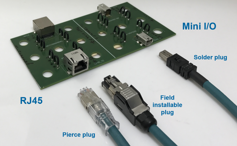
Fig. 1. Example of the different types of tested Ethernet connectors
The RJ45 connector system
Commonly referred to as “RJ45”, the physical connector is standardized as the 8P8C modular connector per IEC60603-7, ANSI/TIA-1096-A and ISO-8877 standards. Wired to the T568A and T568B pinouts specified in the TIA/EIA-568 standard, the RJ45 is compatible with both telephone and Ethernet. The RJ45 is a modular connector that was originally designed for use in telephone wiring. Modular connectors were described in the Registration Interface system in the USA. This was mandated by the Federal Communications Commission (FCC) in 1976 in which they became known as Registered Jacks. The piercing contact used in the RJ45 is the only known principle to reliably connect to tinsel wire, as used in fixed phone coil cords. The modular design made it perfectly suitable for termination to flat cable of various widths. For flat cable the termination speed is still unsurpassed, because all conductors are pierced in one step, and a double cable strain relief is also provided. Unfortunately, the wiring scheme of T567B requires a cross-over of the wires of the round cable, making the termination far less straight forward.
During the past decades, the RJ45 has proven its versatility [1] and is nowadays even used in industrial environments by additional shielding and rugged enclosures.
The Mini I/O connector system
Originally designed for the Japanese industrial market, the Mini I/O was developed to be smaller and more reliable compared to the RJ45. The mating interface envelope reduction was realized by choosing fully enclosed metal shells, which take up the forces, provide tight tolerances and mating interface stability. By using additional multiple solder pads and additional hole anchor pegs, it can withstand 98 N of pull force according product specification, while still being true SMD pick & place. Using a hermaphroditic contact layout, both plug and receptacle contacts have spring action and 2 independent contact points, also known as the “fighting snake contacts”. As the originator, TE Connectivity obtained IEC standardization of Mini I/O for speeds up to 1 Gbps/100m [2]. AMPHENOL and FCI are driving this connector also as a standard for the industrial market.
Methods and results
Test samples used
The connectors are terminated to a common industrial grade Cat 5e cable, having 26AWG [0.13 mm2] wires. The RJ45 receptacles are right angle SMD type Jacks, except for one through hole reflow type. The RJ45 Plugs are pierce or field installable type. All connector brands are tested in pairs; plug and jack are of the same brand, except one pair. For Mini I/O right angle receptacles, SMD version with Type 2 keying were mated to solder version plugs.
After the preparation of the lead assemblies, several poor RJ45 pierce terminations (Rtotal – Rbulk > 20 mΩ) were found immediately at the initial LLCR measurements in the lab. The regular termination quality check with an electrical continuity tool did not reveal these defects. Investigation showed that wire insertion depth and/or load bar depth is very critical to making good pierce terminations. For all RJ45 pierce brands, care must be taken to guarantee correct wire insertion depth when pressing the wire manager into the connector, but some brands are very critical on this aspect.
Contact physics analysis
The RJ45 and Mini I/O contact systems are based on gold over Nickel plating. A comparison is given in fig. 2.

Fig. 2. Comparison of 2 Ethernet connector systems with cross sections of mating interface
Key differences of influence on connection stability per connector type are:
The RJ45 layout:
- Contact point stability; The dimensions and tolerances enforced by the IEC60603 series allow for very large movements of the contact point (worst case up to 1.08 mm in mating direction) and contact normal force variations.
- Single contact point; contact systems with only a single beam / contact point can be very stable [3], but in combination with poor contact point stability induced wear, not having redundancy from parallel contact points shows resistance fluctuations directly. Especially when mating cycle wear is followed by environmental stressing.
- Shear edge connection: The stamping direction of the piercing contact will create a sheared edge on the contact mating surface. Some RJ45 plug contact surfaces are smoothened.
- Wire termination pierce contact principle: during piercing the tool presses on the contact surface, inducing the risk of deforming or damaging the surface.
The Mini I/O layout:
- Contact point stability; the contact point tolerance chain is well controlled. The metal shells allow tighter tolerances and provide more rigidity.
- In the solder version plug and the SMD receptacle, both contacts have smooth rolled surfaces.
- The layout is more complex and requires an elastic spring material on plug and receptacle side.
Performance & Reliability investigation
Test groups were defined for specific performance areas. Each group consists of 4 mated pairs, thus 32 signal contact measurements per group.
Mechanical / vibration / durability
Two test groups were defined were after 375 mating cycles and, either a humidity (21 cycles of -10/25/65°C) or MFG (4 gasses / 21 days) test, was followed by temperature-life and vibration test up to 25g. The target was to induce environmental stressing after wear, so differences between the contact systems could be found without testing too mild or destroying all connections. The increase in Low Level Contact Resistance (ΔLLCR) was one of the outcomes. Initially all signal connections are OK (< 20 mΩ), but large static resistance increases (>300 mΩ) could already be observed after the first 375 mating cycles.
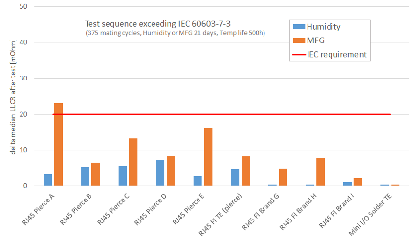
Fig. 3. Increase in signal contact LLCR after mating cycles, environmental stressing and vibration
In the vibration test a special set-up is used to count the micro discontinuities. The aim is to get a measure of how much for each connector the bit errors would increase during vibration. Specification IEC 60603-7, used for Ethernet, states that the product fails when discontinuities happen for more than 10μs. Most industrial networks must have at least Cat 5e performance, that has for every differential pair a baud rate of 125Mbaud. The time-period of every baud is 8ns, so when only discontinuities of 10μs are counted as a fault, a lot of bit errors have occurred already. Therefore, the interruption time in this test is reduced from 10μs to 20ns. This value gets in the range of the time-period of one baud. Then, during the vibration test that continues for 2 hours, every interruption larger than 20ns is counted as a fault.
The results of this discontinuity check is given in fig. 4. All connectors show discontinuities, but when 20 ns discontinuities are counted, a connection quality rating can be given by the total number of discontinuities. This value provides a better understanding of the connector stability in industrial applications.
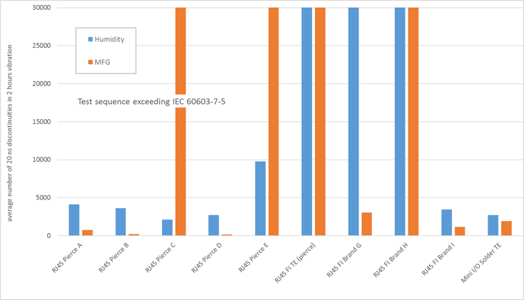
Fig. 4. 20 ns Discontinuities after mating cycles / environmental stressing during vibration, 8 signal contacts in series
Dielectric Withstanding Voltage (DWV)
To find the voltage limits of the connector systems, 2 mated pairs of each group where tested until flashover destroyed the connector. All samples passed IEC requirements with a safety margin of 500 V minimum as is shown in Fig. 5.
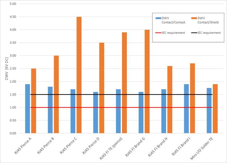
Fig. 5. Dielectric Withstanding Voltage – test until failure
EMI
In the EMI measurements is chosen for the screening attenuation for comparison, to show the EMI performance of the connectors from 1 to 500MHz. In Fig. 6 the results are given. As can be seen, the screening attenuation of the Mini I/O soldered version is significant better than the other RJ45 versions up to the frequency of 125MHz, what is the frequency band of interest for data rates up to 1Gbps. For the frequency range above 125MHz the performance is still one of the best.
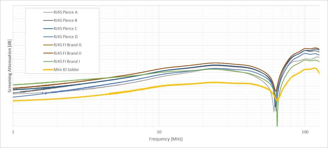
Fig. 6. EMI results
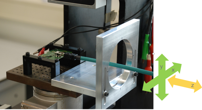
Fig. 7. Cable movement test set-up
Contact Physics: Normal force & resistance
3 consecutive deflections of virgin parts showed normal repeatable characteristics for normal force and resistance vs. deflection. Low and stable initial resistances typical for gold are found for all connectors.
An additional cable movement test was added to investigate interface stability further. This cable movement test shows some resemblance to the automotive LV-214-2 “slow motion bending test”, and monitors the resistance when moving the cable lateral and axial at 100 mm distance from the mating interface. This induces contact point relative motions within the connector interface limits. The influence on the resistance can be seen in Fig. 8.
The mini I/O solder plug combination is the most stable.
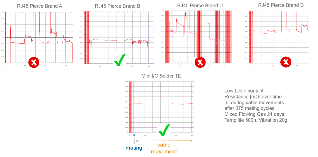
Fig. 8. LLCR during cable movement, test sequence exceeding IEC 60603-7-3
Conclusion
In the broad benchmark described, test combinations and severity are used exceeding the IEC 60603-7-3. Mini I/O solder performed best on several key performance criteria, which are critical for usage in industrial applications:
Short discontinuities during vibration: Low due to a stable mechanical interface and double spring / double contact point layout.
Resistance during cable movement: Very stable flat resistance line during interface motions after environmental stress tests.
EMI: Screening attenuation of the Mini I/O is significantly better compared to all other RJ45 connectors.
These benefits come on top of the other advantages of using Mini-I/O in an Industrial environment: The small size (mating face form factor of only 25% of RJ45) and high board- and cable retention (98 N cable pull force), making Mini-I/O a preferred cable to board connector solution for harsh IP20 environments.
References
[1] R. Hult, Bishop & Associates Inc., http://www.connectorsupplier.com/praise-for-the-lowly-modular-plug/
[2] IEC 61076-3-122/Ed.1.0 2017-05, Part 3-122: “Detail specification for 8-way, shielded, free and fixed connectors for I/O and Gigabit applications in harsh environments.”
[3] J. Broeksteeg, IMAPS 2008, “Design of a high performance single beam contact for demanding and long life time applications in Industry and Telecom markets”
More information
Industrial mini I/O website