Sorting out Drills and Cutouts
Components, connectors, cases, cables, modules, and other things that get attached to our PCBs may require space that isn’t a simple round drill hole. For those special gaps we create cutouts.
Let’s first define what we’re talking about because there’s no industry consensus on some of these terms. We can distinguish between two types of shapes taken away from the material:
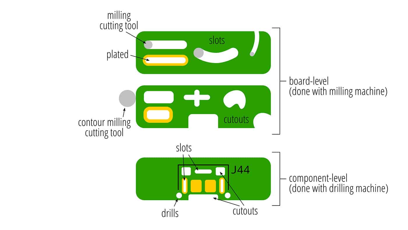
Drill: a circular hole that goes through the board and that can be done with a round drill bit.
Cutout: any shape of hole that isn’t a drill.
As a subset of cutouts we’ll also define:
Slot: a cutout of a constant width equal to the diameter of a round cutting bit; it is defined as a single movement from start- to end-point.
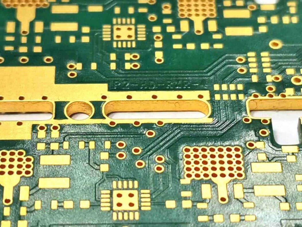
Drills and cutouts can be completely internal to the PCB (within its contour) or overlap with the contour so it appears to be part of the contour when the PCB is made. The contour itself is milled using a round cutting tool, typically 2mm in diameter. (For our purposes contour milling and routing are interchangeable, but we prefer to use milling to better distinguish it from routing of signals, a completely different PCB design topic.)
We can now further refine our definitions into two types:
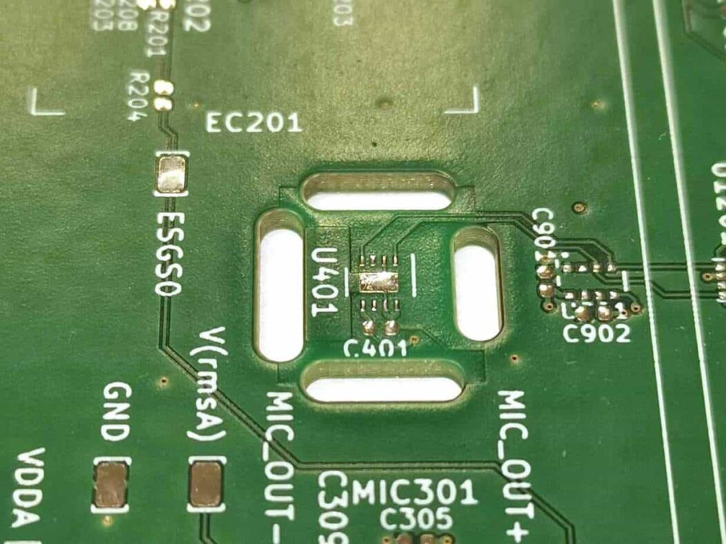
Component-level: drills and cutouts that are defined as part of a component in the PCB design tool, and that are included in a drill file supplied to the manufacturer.
Board-level: drills and cutouts that are defined as part of the contour of the board, or on a mechanical layer and do not appear in a drill file.
With these definitions out of the way we can continue our discussion.
How cutouts are manufactured
As designers it’s tempting to think that drills and cutouts are roughly the same thing: you either drill or drill and move in the X-Y axis (what we call milling as above). Well, it’s not that simple, as I keep saying of topics I chose to cover.
To fully understand how our drills and cutouts are made let’s define the following two phases in the manufacturing process:
Drilling-phase: performed at the beginning of the manufacturing process, usually before imaging of the external copper. It requires very tight tolerances to best match the tolerances of imaging of the copper features.
Milling-phase: normally performed at the very end of the manufacturing process with more relaxed mechanical tolerances compared to drilling. (Eurocircuits’ current Profile Dimensional Tolerance is 0.20mm which could not possibly work for the drilling-phase considering copper feature sizes.)
Now, even though the process of drilling and milling are usually performed with different machines we can assume that they have the same capabilities and attributes. It needs to be that way because although we call it a drilling-phase, some milling is also performed then and we’ll talk about this shortly.
As we’ve mentioned, milling-phase operations have a lower tolerance specification than those in the drilling-phase. This is because of two reasons. Firstly, the forces that milling (movement in the X-Y direction) exerts on the spindle head causes it to lose accuracy over time, faster than it would if it had only performed drilling. And secondly, the positional holes used to place the panel on the milling machine were created in the drilling-phase. That means that throughout the manufacturing process the milling position could slightly shift, affecting the positional tolerance of the milling-phase.
Why should a designer care about all this?
Fair question. The reason dawned on me while researching for this article: if we want maximum cutout accuracy and tighter tolerances with respect to other features (drills, pads, other cutouts, etc.) we’d like them to be done in the drill-phase! Drills, plated or not, are done at that phase by default. To make sure that cutouts are done at that phase as well we can define them as plated or include them in the drill file by defining them as part of a component, or component-level cutouts. (Providing Gerber X2/X3 drill files helps the manufacturer correctly process drills and cutouts because it has more specific information than older formats; use those where possible.)
Component-level cutout definition is beneficial in two ways. Firstly, it keeps the distance tolerance between features of the same component as low as possible. And, if the designer moves the component in their design tool, the drills and cutouts move with it, whereas board-level cutouts would not.
Routing and milling at Eurocircuits
As always, good results depend on unambiguous data and communication: consult our page about how to best indicate slots and cutouts in the process of ordering PCBs from us.
Bring your product to market on time and within budget – join the Eurocircuits Community


![]()

