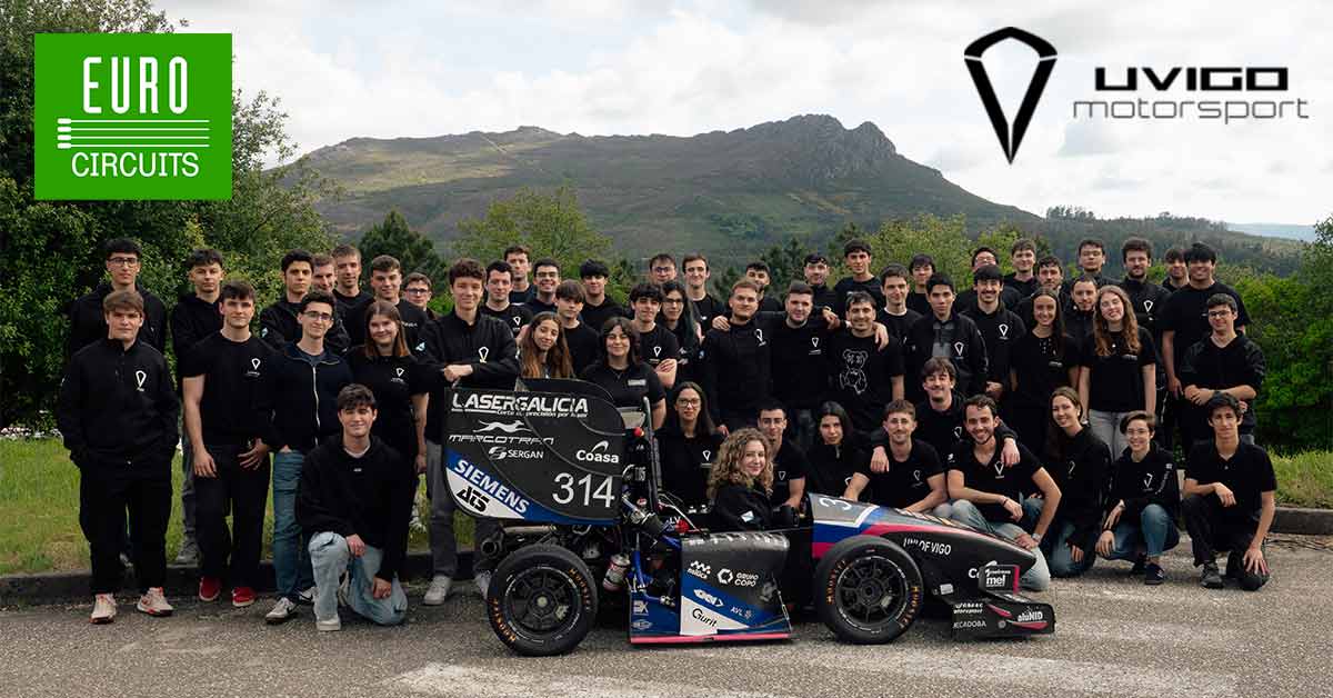
Dynamis PRC – Formula Student Team

Bring your product to market on time and within budget – join the Eurocircuits Community

Dynamis-PRC-Blog-Banner

Team Presentation Dynamis PRC

Dynamis PRC is a Formula student team of Politecnico di Milano.
In 2020 we started developing our first electric prototype with which we are going to compete in the summer of 2021.

In last year’s competitions, Dynamis PRC took part in 4 European competitions with our DP11 prototype. We went to the Netherlands, Hungary, Italy and Germany.
We achieved fantastic results, winning the Dutch and Italian competition and reaching a third place in the FSG event.

After those amazing results, we decided to begin a new challenge in the electric world.

Moving from the combustion to the electric world we get into some challenges, but we are very proud of the results we have obtained. The main work of the Electronics & Powertrain department can be subdivided in two main parts: a low voltage one and a high voltage one.

Dynamis-PRC-Low&High-Voltage-CAD

Low voltage & High voltage CAD


Low Voltage

To get a better focus on the new challenges, the most reliable elements in the previous year’s design were kept and eventually improved and adapted. Therefore, the low voltage system was kept at a working voltage of 12V, as in the previous combustion prototype, in order to reduce the necessary changes in the design of the system.

Having four in-wheel independent motors opened the possibility of implementing more sophisticated vehicle dynamics control techniques, such as torque vectoring and slip control. Thus, the need for a dedicated Vehicle Control Unit and more reliable sensors. Moreover, in the last season, many issues were caused by different families of microcontrollers mounted on the PCBs.

One of the aims for the new prototype was to solve these problems by aligning all MCUs. To enhance the system’s modularity, the LV electronics is divided in four subsystems:

  • LV Power Supply and Wire Harness
  • Vehicle and Dynamics Control System
  • Driver Interface
  • Data Management System

The low voltage part has the goal to manage all the things that involve the control of the vehicle, the data acquisition, the data management (saving and sending data to the telemetry station) and the power supply to all the boards and sensors.

The electronics consists of custom, own developed boards with ST micros, sensors and modules including a real time telemetry system with XBEE system, power distribution module, INSS-GNSS positioning and a steering wheel with 3.5’’ colour display.
All the boards and modules inside the vehicle communicate via a CAN BUS.

The entire wiring harness is self-made, and we follow the concentric twisting techniques which give us high reliability and robustness. From last year we will take the additional requirements introduced by the transition to the electrical formula student category, such as the presence of further disturbances introduced by the electrical motors.


High Voltage

The new challenges of the electric category can be summed up in three main subsystems:

  • Accumulator
  • BMS
  • Inverters and motors

The starting point of the design was to set the main Accumulator parameters. Simulation results of the vehicle model brought to us by the Vehicle Dynamics Department indicated that an accumulator with a minimum energy storage of 7WKh and an average output power of 30kW was needed. The accumulator Maximum Voltage was set by the Inverter specs and by the idea of reducing the average Accumulator Output Current to lower power loss.  The cells adopted were the Sony VTC6, composed as a 1s5p block provided by Energus Power Solution, which featured integrated temperature measuring sensors and gave us to possibility to avoid cell assembling issue. After the decision of the accumulator parameters, we started developing a home-made BMS system.

The BMS System has been designed aiming for the best solution in terms of immunity to EMI and safety in interfacing with the Tractive System. These guidelines led to a decentralized System, composed of one Master Unit, hosting only Low Voltage Power Domain, and six Slave units, galvanically isolated from the Low Voltage System and directly supplied by the battery cells. Slaves are connected in daisy chain and communicates through an isoSPI BUS, terminated on the Master Unit. Slave Units monitor cell Voltages, cell Temperatures and perform passive balancing during a charging session. These operations are carried out by a LTC6812 battery stack monitor. Acquired data are sent to the Master Unit, based on a STM32 ARM-M7 microcontroller, which performs conversion, monitoring and communication with the other electronic systems in the vehicle via the main CAN Bus. The Master also provides the possibility to interface the BMS System with external laptop through an isolated USB port, and oversees the charging session interfacing with the charger via an auxiliary CAN Bus.

For the inverters and motors, as it is our first year in the electric category, we decided to take the AMK set of 4 motors and inverters. The work that we done is a Simulink model created to simulate how the inverters work. This model was useful for comparing different choices and providing, through its integration with ViGrade, data regarding the power consumption of engines and inverters in various modes of operation. The model has been structured for torque control of the engines, with the ability to insert several field weakening functions into the control. Limiters and derating were added to represent the true inverter as closely as possible. An evolution of this model will replace control blocks with IGBT’s H-bridge circuits. This choice was not initially considered, although it could provide us with more precise data, because it was important to develop the model as quickly as possible so that we could have a comparison with the equation derived.


Eurocircuits’ Support to Dynamis PRC

Moving to the electric category we get into the design of more PCBs than before. Especially the PCBs of the BMS Slaves, the Steering Wheel and the TSAL.

BMS Slave

Due to demanding space requirements, the design of battery required that the 132 cells are distributed unevenly across the 6 segments. In order to reduce also the cost of production and design we chose to design just one BMS Slave board that satisfied the management of both 24-cell segments and 18-cell segments. To achieve this, result a few components are required to be soldered or not soldered by the user.

Steering Wheel

The main constraint is the physical one: the electronics must be securely mounted inside of the carbon fibre shell. This posed a limit on the size of the internal boards. The internal electronic boards must also be easy to replace or to work on if a malfunction occurs, and this feature must be considered in the design.

Tsal

The aim of the Tractive System Active Light (TSAL) is to indicate TS state, depending on specific signals coming from accumulator container: particularly, green LEDs on show a safe state active (TS Off), while blinking red LEDs shows a potentially dangerous situation (TS on).
The main assembly is composed by two main parts: TSAL LV, that contains all LV control logic and LED lights, and TSAL HV, that interfaces HV accumulator signals with LV part. Related to the project there are also dummy TSAL, used to simulate TSAL signals when main board is disconnected, and indicators board, that shows to the driver TS safe state with a green light placed in the cockpit.

Dynamis-PRC-BMS-Slave

BMS Slave

Dynamis-PRC-Steering-Wheel-PCB

Steering Wheel Circuit Board

Dynamis-PRC-TSAL-PCB

TSAL Circuit Board

Dynamis-PRC-Logo

For more information, please visit our website Dynamis PRC

Be the first to read all about our news and information. Follow us on