Finished Hole Size Tolerances
There are 3 types of holes on a PCB, Plated, Non-Plated and Via’s and they have different Finished Hole Size tolerances based on their type and size.
Finished Hole Size tolerances are based upon the following factors:
- Type of Hole – Plated, Non-Plated or Via.
- Nominal Hole Size vs available Drill Bit Sizes.
- Drill Bit Size Tolerance.
- Drill Bit Wear during use.
- Hole Cleaning (Desmear).
- The Plating Process and Copper Balance.
- The Final Surface Finish of the PCB.
When a hole is to be plated it is drilled over-size to allow for the manufacturing tolerances and downstream plating process.
The over-size value is determined by the plated copper thickness and known accumulated manufacturing tolerances.
Nominal Hole Size vs available Drill Bit Sizes
The defined tolerances start with the drill bits, these are available in standard size steps of 0.05mm and any hole defined in a CAD system that does not meet this 0.05mm step will be rounded to the nearest step.
It is possible to have smaller drill bit size steps however, their high cost these usually outweighs their advantage.
Looking at it from another point of view, we are talking about a rounding with a maximum value of 0.025mm or 25µm.
This should not cause any downstream process issues.
Drill Bit Size Tolerance
Drill bits are machined and thus have a tolerance on the size as defined in the manufacturers data sheets.
The standard tolerance quoted by our supplier varies from 0.003mm to 0.010mm depending on the size of the drill bit.
Drill Bit Wear
During the process of drilling holes friction is created and this leads to the wear of the drill bit, this is a very small amount (in the microns) and the drill bit is replaced regularly based on the known wear rate.
However, it still must be considered as part of the tolerances accumulated during the manufacture of a PCB.
The Hole Cleaning (Desmear)
After the holes have been drilled they need to be cleaned.
This is to remove any particles that were left in them by the drilling process.
Cleaning is a chemical process, known as desmear, it also smooths the hole walls ready for the black hole treatment.
During the cleaning a very small amount (less than a micron) of the hole wall is removed, thus increasing the hole diameter.
If the cleaning is not performed correctly then the black hole process may fail and so would the plating process.
The Plating of Holes and the Copper Balance
The plating of holes on a PCB is a critical part of the manufacturing process.
Get it wrong and the interconnections between the layers would fail or a least be unreliable as would the solder-ability of the component leads in these holes.
Our target is to deposit approximately 20-25µm of copper in the plated through holes.
However, the Copper Balance of a PCB greatly influences how evenly the copper is distributed across the whole PCB.
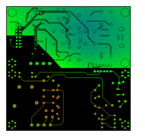
The copper distribution shown below would lead to more copper being deposited in areas with less copper density (red).
Resulting in the holes is this area having thicker copper walls and thus a smaller actual finished hole size.
For more information on how to improve the copper balance please see our Tips & Tricks post on How to achieve a more even copper density.
The Final Surface Finish of the PCB
When we talk about the Final Surface Finish we are, referring to the final metallised protective finish for pads and exposed copper on a PCB after Soldermask, this may be HAL, ENIG, ImAg etc.
Any plated holes not covered by Soldermask will be plated during the Final Surface Finish process and thus these holes will have a further reduction in size.

