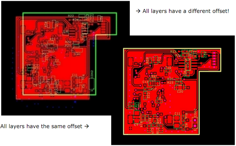
10 Rules for Better Data – Avoid PCB Design Issues

Introduction

We derived these 10 rules for better data from the most common issues we encounter in our daily frontend engineering process.

Keeping some simple rules in mind can avoid delays due to data issues after you have placed the order.


  • Rule Number 1


    • Do not scale your data.
    • All data provided must be scale 1/1 (100 %).


  • Rule Number 2


    • Make sure that your DO NOT contain apertures with a zero-size (size =0.00 mm or inches).
    • Your Excellon data DOES NOT have zero sized tools ( size=0.00mm or inches).


  • Rule Number 3


    • Use the same offset for all your Gerber layers and the Excellon drill data. Preferably use no offset at all.Layers with same versus different offset


  • Rule Number 4


    • Use the same units (mm or inch) in your Gerber & Excellon output files as in your CAD PCB design software as this will eliminate conversion or rounding errors.


  • Rule Number 5


    • Use the same resolution (grid) for your Gerber & Excellon data to allow a perfect match.
    • Set the resolution (grid) for output (Gerber & Excellon) to 6 decimals using the imperial system and 5 to decimals using the metric system as recommended in the Gerber specification.
    • If your CAD system supports only lower resolutions than what is recommended then use the highest available number of decimals.


  • Rule Number 6


    • Make sure that your data is supplied as seen from top to bottom through the PCB.
    • DO NOT mirror (or reflect) any data layer – image or drill.
    • Viewing a PCB from top to bottom through the board is the universal practice in the PCB industry.
      • This means that when viewing your Gerber data, text on the top side of your board (copper,
        soldermask, legend) should be readable and text on the bottom side
        (copper, soldermask, legend) should be non-readable (= mirrored).

      Viewing PCB top to bottom


  • Rule Number 7


    • Put some small text (board identification, company name, etc…) in the copper layers.
    • Make sure the text complies with the readability rules. (Rule number 6) as this will help us to avoid mirroring errors.


  • Rule Number 8


    • RECOMMENDATION – In your Gerber files use flashed pads as wherever possible.


  • Rule Number 9


    • RECOMMENDATION – In your CAD PCB design software try to create an aperture list for Gerber output
      which only shows the apertures that are used in the design.


  • Rule Number 10


    • Make sure that you include the board outline on all layers. This will enable us to properly align all layers in case
      of an offset problem.
    • Also include the board outline in a separate Gerber mechanical plan.


Page Update History


Other ways to find help

User Guides

Our User Guides provide step-by-step instructions on how to use our free online smart tools and other available software.
View all 5 user guides

Glossary

To simplify communication Eurocircuits uses abbreviations for many of these technical terms. Most of the technical terms and abbreviations are international standards in the Printed Circuit Board manufacturing industry. However to make it clear to everyone involved, we here present a list of technical terms and abbreviations along with their explanation.
View our glossary

Still need help?

Talk to our customer support via our online chat, telephone or email.
Contact us